Program "TRASSE"
From BAWiki
Planning fairways in channels with negligible flow velocities
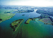
For planning canals or fairways in non-running waters, the German Federal Waterways and Shipping Administration (WSV) can rely on the “Richtlinien für Regelquerschnitte von Schifffahrtskanälen” (guidelines for standard cross-sections of navigation canals) introduced in 1994 by decree BW24/BW23/BW28/52.05.00/16/VA94 of the German Federal Ministry of Transport (BMV). In the course of planning the transportation project “German Reunification” No. 17 (VDE 17) – consisting of the development of the waterways between Hanover and Berlin into a waterway Category Vb – it quickly became obvious that the development targets given in the guidelines cannot be realised. Vital sections of the waterway to be developed run through natural river environments and protected or “Fauna-Flora-Habitat (FFH)” areas and within the city borders of Berlin where building has even reached the current river banks. These conditions require that future fairways must more or less follow the current course of the fairway; this means that the aimed minimum radii of 600 m cannot be met in curvatures. As a result, new alignment tools had to be developed when starting planning for the VDE 17 project.
Purpose of the software
Local conditions within the VDE 17 section which is to be developed led to the following requirements for the routing procedure to be developed:
- Reference vessels are the 185 m long push-tow-unit, the 110 m long large motor vessel and the 85 m long “Europe Ship”.
- It must be possible to consider fairway radii ranging from a straight course to radii of 200 m.
- It must be guaranteed that differences in the dynamics of ship movement and the related effects on swept area widths can be taken into account when entering and leaving curves, especially in curves with small radii, small central angles and curvatures changing from right to left.
- The procedure must be quickly available and easy to apply.
- It should be possible to integrate the alignment results into MicroStation, the CAD system of the WSV.
Theoretical basis of the procedure
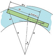

In the above guidelines for standard cross-sections of navigation canals, the fairway width is composed of the swept area width of the reference vessels and of the safety distances between vessel and bank. Here fixed values are given for the security distances as well as for the swept area width of the vessels when moving straight ahead. For curvatures of radii under 2000 m, the widening of the swept area is calculated using the Graewe formula (published in the magazine Bautechnik 1/1971). The formula is:
[math]\displaystyle{ B1 = \sqrt{(R+B)^2 + \left[\frac{L}{2} + \left(R+\frac{B}{2}\right) * tan(\beta)\right]^2 } -R }[/math]
with:
B1 - swept area width [m]
R – inner curve radius [m]
L – vessel length [m]
B – vessel width [m]
β – drift angle
In addition to this calculation rule for the radius range between 600 m and 2000 m, drift angles are given which must be added to the formula
The procedure called “TRASSE” has been developed as a consequence of the planning requirements of the VDE 17 project within the city borders of Berlin. Here the radii had to be much lower than the targeted minimum radii of 600 m. On principle, like the Graewe formula, the TRASSE procedure is based on the Pythagorean theorem.
As we can see in Figure 2 a rectangular triangle is positioned with the right angle outboard at the pivot point position; this is the point where the lateral approach flow onto the ship body changes its direction. The acute angles are located in the centre of the turning circle or at the stern of the vessel. Apart from the B1 swept area width one is looking for, almost all the parameters result from the ship or curve geometry. The drift angle which helps to calculate the distance between the stern of the vessel and the pivot point position can be determined by in-situ measurements.
This calculation which applies the Graewe formula can be simplified by introducing a non-dimensional coefficient Cf which, multiplied with the vessel length, also provides the distance between the stern and the pivot point position.
[math]\displaystyle{ B1 = \sqrt{(R+B)^2 + (Cf * L)^2} -R }[/math]
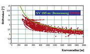
While developing the model, numerous in-situ studies on the dynamics of ship movement were performed. This involved the measurement of different vessel types and loading conditions and related drift angles dependent on the curve radii (Figure 3). Following this, the drift angles were converted into the non-dimensional value Cf, whereby it could be stated that the coefficient does not depend on the radius driven (Figure 4). This applies up to the smallest radius driven of one vessel length.
Both calculation procedures only allow a generalised calculation of swept area widths when moving in curves. Information is still lacking about how to design the transitions between the straight line and the arc of a circle or the swept area width in curves with small central angles. To answer this question was one of the development objectives.
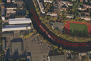
During further development of the procedure, we made use of the fact that at the pivot point position the vessel with its pivot point always “drives to its course axis” in a tangential manner. When moving a rectangular symbol that has the dimensions of the reference vessel and has its reference point at the pivot point position in a tangential way along a course axis constructed before, a tractrix is formed from the numerous rectangular symbols and this corresponds to the swept area of a vessel. In-situ studies confirmed the correctness of this procedure (Figure 5).
These tractrixes automatically allow for the differences in the nautical behaviour of vessels when entering a curve compared to leaving a curve. Like in curves with small central angles, the necessary fairway widening measures do not become as fully effective as the generalised calculation using the above formulas would require. For such situations, reductions are calculated accordingly. In the same way, the fairway courses can be constructed for areas with curvatures which directly follow each other.
For easier integration of the calculation results into the MicroStation alignment environment, the construction steps were processed so that they could be programmed directly as a MicroStation application. In the end we received a concise tool enabling the planning of fairways within the working environment of the WSV.
Description of the TRASSE working steps using an application example


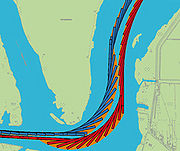
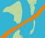

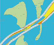
The various steps will be explained using the example of aligning the Flusshavel. Necessary input data are the digital Federal Waterways map (Digitale Bundeswasserstraßenkarte, DBWK), a Digital Terrain Model (DTM) of the original state of the river bed with the related bank area as well as the dimensions of the reference vessels with the appropriate Cf values (coefficient for calculating the distance between stern and pivot point).
A first step consists of constructing the course axes on the maps along which the reference vessels should "drive" (Figure 6).
When constructing the course axes, it must be guaranteed that the axes consist only of straight lines and arcs of a circle alternating and fusing in a tangential way. These conditions are necessary in order to maintain the characteristics of inland vessels for ship movement dynamics despite the strong simplification of the mathematical model. Using the MicroStation extensions InRail or InRoad, these types of course axes can quickly be drawn and manipulated with their alignment tools.
When constructing the axes, it must be considered that their distance to the right bank must be large enough to guarantee the prescribed safety distances between the tractrix of the reference vessel and the bank. In addition, the distance between the course axes of up- and downstream vessels must be large enough to allow for the required safety distance between the tractrixes as well. Once the course axes are drawn, the tractrixes will be calculated.
Figure 7 shows the meeting of two push-tow-units 185 m long. The blue push-tow-unit moves downstream and the red one upstream. If once the tractrixes are created, areas can be identified where the waterways development targets or the aimed distances between the vessels or to the banks are not respected, then the course axes must be manipulated accordingly. Manipulating course axes will be continued until the aimed safety distances are met or the necessary measures at the banks minimised. Once the tractrixes meet all requirements the swept area widths will be determined.
Figure 8 shows the meeting of two push-tow-units near Deetzer Knies. Constructing envelope curves around the tractrixes of ship symbols gives way to areas corresponding to the respective swept area of the vessel.
When moving straight ahead the vessel width is equal to the swept area width. However this does not correspond to real conditions, since a ship cannot go straight ahead, but instead follows the planned route on a sinusoidal shaped line. In order to take this increased need of traffic area into account, the envelope curves have a minimum distance to each other. If the tractrix remains under this minimum distance, the envelope curves move away from the ship symbols on both sides each time by a distance of half the missing width. The additional width caused by moving along a sinusoidal line when travelling in curves is already taken into account in the Cf value. Appropriate numerical routines exist for creating the envelope curves.
The traffic area requirements for the meeting of both push-tow-units are determined on the basis of both swept areas (Figure 9). And a terrain model of the new fairway is calculated and integrated into the original terrain model (Figure 10).
Finally, the necessary dredging volumes in the fairway (bottom and slope separated) and the importance of the necessary setting-back of banks can be calculated by matching the original terrain with the model of the new fairways (Figure 11).
Reference projects
Thanks to the easy handling of the software, the “TRASSE” programme has now been used in public administration as well. Examples of projects using “TRASSE” since the procedure’s introduction include:
| Project | Executing authority |
|---|---|
| VDE 17; Alignment of Spreebögen | BAW |
| Alignment of Havel-Oder waterway | WSA (local Waterways and Shipping Office) Eberswalde |
| VDE 17; (Lower Havel Waterway) - Flusshavel | (Wasserstraßen-Neubauamt/ Waterways Construction Office) Berlin / BAW |
| VDE 17; Britzer Zweigkanal (Britz secondary arm of canal) | BAW |
| Veltener Stichkanal (Velten branch canal) | BAW |
| VDE 17; Spandau crossing | BAW |
| VDE 17; Jungfernsee | (Wasserstraßen-Neubauamt/ Waterways Construction Office) Berlin |
| Schleuse Storkow lock | BAW |
| Trafficability analysis of River Saar for hydrostatic congestion | Corporate Montage/BAW |
| VDE 17; Brandenburger Seen (Brandenburg lakes) | WNA (Wasserstraßen-Neubauamt/ Waterways Construction Office) Berlin |
| Access to Bolzum lock | NBA (Neubauamt / Construction Office) Hannover |
| Dortmund-Ems Canal, Section in the City of Emden | BAW |
back to Programs for Vessel Movement Dynamics
