Ship-generated Loading: Difference between revisions
From BAWiki
| Line 23: | Line 23: | ||
==Functional Relationships== | ==Functional Relationships== | ||
[[de:Funktionelle Abhängigkeiten]] | |||
The parameters for the water level and current variations caused by a moving ship are a function of: | |||
* ship velocity '''v<sub>S</sub>''' and the passing distance '''L''' | |||
* ship dimensions (length '''l''', width '''b''', draught '''t''', submerged midship cross-section '''A<sub>S</sub>''') | |||
* total hydrodynamic resistance of the ship (ship form) in the canal '''R<sub>T,K</sub>''' | |||
* waterway conditions (water level '''B''' and bed width '''B<sub>S</sub>''', water depth '''d''', cross-section and area '''A''', bank profile and slope '''1 : m''') | |||
* current conditions in the waterway | |||
* other influences such as waterway bend, type of propulsion, water density. | |||
<br /> | |||
The ''essential'' parameters for the ship induced loading for fairways have been shown to be: | |||
* the ship velocity ('''v<sub>S</sub>''') | |||
* the passing distance ('''L''') to the bank edge which defines the hydraulic partial cross-section ('''A<sub>T</sub>''') | |||
* the water depth to draught ratio ('''d/t'''), and the cross-section ratio '''A<sub>T</sub> / 0,5 A<sub>S</sub>'''. | |||
To illustrate more simply the physical processes occurring when a ship is moving in a waterway of varying non-uniform cross-section, one may think of the waterway cross-section as being divided into two parts '''A<sub>T1</sub>''' and '''A<sub>T2</sub>''', through each of which half of the ship's displacement passes. Thus each bank experiences a qualitatively different ship induced loading as is determined by the partial cross-section ratios '''A<sub>T1</sub> / 0,5 A<sub>S</sub>''' and '''A<sub>T2</sub> / 0,5 A<sub>S</sub>'''. | |||
<br /> | |||
==Analytical and Empirical Methods== | ==Analytical and Empirical Methods== | ||
==Hydrodynamic Numerical Methods== | ==Hydrodynamic Numerical Methods== | ||
Revision as of 10:29, 7 April 2022
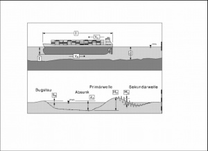
The change in draught- and speed-related ship-induced loading on the shipping routes entails a definition of the characteristic parameters (e.g. ship wave system, displacement current) and requires knowledge of the functional relationships (e.g. ship speed and vessel width, shipping channel conditions, passing clearance). Picture 1 shows a diagram of the ship wave system among others.
Since the start of the new century, a large number of analytical and empirical methods have been developed for calculating the interaction of ship and waterway. Initial calculations with hydrodynamic-numerical models reveal deviations compared to the results of hydraulic scale models, so that these numerical models cannot yet be viewed as a confirmed scientific aid for determining upgrading-related changes to ship-induced loading in shipping channels. At the moment, it is only possible to make confirmed quantitative predictions of ship-induced loadings in inhomogeneous waterways by means of hydraulic model tests in a scientifically confirmed model scale (state-of-the-art engineering and science).
In recent years, the BAW Hamburg office has looked at the issue of the interaction between seagoing ship and tidal fairways both with studies on hydraulic models and with field study measurements.
Definition of the Characteristic Parameters

A moving ship generates waves of different periods as a consequence of its displacement current causing pressure and water level changes at its bow, stern and alongside its hull. The following parameters describe the ship wave and current system, for example, for a ship moving in an estuary at subcritical speed (ship speed less than the phase speed of the prevailing waves):
- the bow pressure (sB) directly at the hull,
- the water level depression (zA) at the side of the ship,
- the stern wave (HP) which is a part of the long period primary wave system,
- the secondary wave superimposed on the primary wave system (HS),
- velocity (vR) of the simultaneously occurring return current.
The water level changes for a depth- and width-limited waterway, as seen by an observer from the bank, are shown as a vertically exaggerated sideview in the above sketch.
Functional Relationships
The parameters for the water level and current variations caused by a moving ship are a function of:
- ship velocity vS and the passing distance L
- ship dimensions (length l, width b, draught t, submerged midship cross-section AS)
- total hydrodynamic resistance of the ship (ship form) in the canal RT,K
- waterway conditions (water level B and bed width BS, water depth d, cross-section and area A, bank profile and slope 1 : m)
- current conditions in the waterway
- other influences such as waterway bend, type of propulsion, water density.
The essential parameters for the ship induced loading for fairways have been shown to be:
- the ship velocity (vS)
- the passing distance (L) to the bank edge which defines the hydraulic partial cross-section (AT)
- the water depth to draught ratio (d/t), and the cross-section ratio AT / 0,5 AS.
To illustrate more simply the physical processes occurring when a ship is moving in a waterway of varying non-uniform cross-section, one may think of the waterway cross-section as being divided into two parts AT1 and AT2, through each of which half of the ship's displacement passes. Thus each bank experiences a qualitatively different ship induced loading as is determined by the partial cross-section ratios AT1 / 0,5 AS and AT2 / 0,5 AS.
Analytical and Empirical Methods
Hydrodynamic Numerical Methods
Author: K. Uliczka
- Definition of the Characteristic Parameters
- Functional Relationships
- Analytical and Empirical Methods
- Hydrodynamic Numerical Methods
back to Hydraulic Modelling
