Shear strength of concrete and masonry: Difference between revisions
From BAWiki
Created page with "The coefficient of friction in construction and concreting joints in hydraulic structures made from unreinforced concrete or masonry can be determined by shear-testing samples..." |
No edit summary |
||
| Line 1: | Line 1: | ||
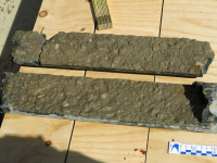
The coefficient of friction in construction and concreting joints in hydraulic structures made from unreinforced concrete or masonry can be determined by shear-testing samples of the structure taken from the joints. | [[File:11_Scherfestigkeit_01.jpg|200px|thumb|right|Picture 1: Sample drilled out of a horizontal joint]]The coefficient of friction in construction and concreting joints in hydraulic structures made from unreinforced concrete or masonry can be determined by shear-testing samples of the structure taken from the joints. | ||
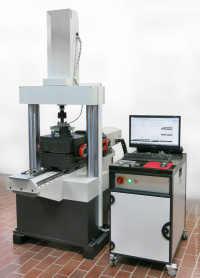
A large number of existing hydraulic structures are made from unreinforced concrete and masonry, both traditional construction methods for discharging normal forces. In the case of hydraulic structures, however, these structures often have to safely discharge high horizontal loads (shear loads) from earth and water pressure, e.g. at locks, weirs, seawalls and dams. In order to quantify resistance capability in construction and concreting joints in concrete structures of this kind, in joints in masonry constructions and in corresponding design sections in the bulk material, the size of the coefficient of friction – potentially in combination with corresponding cohesion components – is therefore crucial. | [[File:11_Scherfestigkeit_02.jpg|200px|thumb|right|Picture 2: Shear test apparatus]]A large number of existing hydraulic structures are made from unreinforced concrete and masonry, both traditional construction methods for discharging normal forces. In the case of hydraulic structures, however, these structures often have to safely discharge high horizontal loads (shear loads) from earth and water pressure, e.g. at locks, weirs, seawalls and dams. In order to quantify resistance capability in construction and concreting joints in concrete structures of this kind, in joints in masonry constructions and in corresponding design sections in the bulk material, the size of the coefficient of friction – potentially in combination with corresponding cohesion components – is therefore crucial. | ||
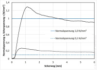
The actual coefficients of friction are not usually available, while the coefficients that are available based on the verification methods currently applicable to concrete structures are often highly unsuitable for the hydraulic structures mentioned. It therefore has to be possible to run tests to determine the shear strength of samples drilled out of the structure’s joints under the corresponding load conditions that actually apply. | [[File:11_Scherfestigkeit_03.jpg|200px|thumb|right|Picture 3: Stress diagram from the shear test]]The actual coefficients of friction are not usually available, while the coefficients that are available based on the verification methods currently applicable to concrete structures are often highly unsuitable for the hydraulic structures mentioned. It therefore has to be possible to run tests to determine the shear strength of samples drilled out of the structure’s joints under the corresponding load conditions that actually apply. | ||
The tests run in the BAW’s construction materials laboratory are based on rock tests and use a direct shear apparatus. First of all, the sample from the structure is fitted into a two-part sample holder in such a way that it can be sheared off horizontally (in the joint). A constant normal stress that is in line with the structural conditions is then applied to the sample in a vertical direction relative to the shear surface and the sample is then sheared off by being moved horizontally at a constant speed. The coefficient of friction can be calculated from the shear stress recorded along the shearing path during the shearing-off process. | The tests run in the BAW’s construction materials laboratory are based on rock tests and use a direct shear apparatus. First of all, the sample from the structure is fitted into a two-part sample holder in such a way that it can be sheared off horizontally (in the joint). A constant normal stress that is in line with the structural conditions is then applied to the sample in a vertical direction relative to the shear surface and the sample is then sheared off by being moved horizontally at a constant speed. The coefficient of friction can be calculated from the shear stress recorded along the shearing path during the shearing-off process. | ||
Revision as of 12:32, 24 March 2022

The coefficient of friction in construction and concreting joints in hydraulic structures made from unreinforced concrete or masonry can be determined by shear-testing samples of the structure taken from the joints.

A large number of existing hydraulic structures are made from unreinforced concrete and masonry, both traditional construction methods for discharging normal forces. In the case of hydraulic structures, however, these structures often have to safely discharge high horizontal loads (shear loads) from earth and water pressure, e.g. at locks, weirs, seawalls and dams. In order to quantify resistance capability in construction and concreting joints in concrete structures of this kind, in joints in masonry constructions and in corresponding design sections in the bulk material, the size of the coefficient of friction – potentially in combination with corresponding cohesion components – is therefore crucial.

The actual coefficients of friction are not usually available, while the coefficients that are available based on the verification methods currently applicable to concrete structures are often highly unsuitable for the hydraulic structures mentioned. It therefore has to be possible to run tests to determine the shear strength of samples drilled out of the structure’s joints under the corresponding load conditions that actually apply.
The tests run in the BAW’s construction materials laboratory are based on rock tests and use a direct shear apparatus. First of all, the sample from the structure is fitted into a two-part sample holder in such a way that it can be sheared off horizontally (in the joint). A constant normal stress that is in line with the structural conditions is then applied to the sample in a vertical direction relative to the shear surface and the sample is then sheared off by being moved horizontally at a constant speed. The coefficient of friction can be calculated from the shear stress recorded along the shearing path during the shearing-off process.
back to: Structural Engineering Methods
