Interaction of ground and building structure: Difference between revisions
From BAWiki
No edit summary |
The LinkTitles extension automatically added links to existing pages (<a target="_blank" rel="nofollow noreferrer noopener" class="external free" href="https://github.com/bovender/LinkTitles">https://github.com/bovender/LinkTitles</a>). |
||
| (One intermediate revision by one other user not shown) | |||
| Line 1: | Line 1: | ||
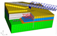
[[File:06_Numerische_V_02.jpg|200px|thumb|right|Picture 1: 3D model of the excavation pit for Sülfeld lock]]Deformation and stability calculations for building structures used in waterways engineering are increasingly carried out using the finite element method (FEM) and in recent years also the distinct element method (DEM). The advantage of FEM is that it can be used to visualize complex geometries and ground conditions, and also indicates interaction between building structure and the ground. | [[File:06_Numerische_V_02.jpg|200px|thumb|right|Picture 1: 3D model of the excavation pit for Sülfeld lock]]Deformation and stability calculations for [[building]] structures used in waterways engineering are increasingly carried out using the finite element method (FEM) and in recent years also the distinct element method (DEM). The advantage of FEM is that it can be used to visualize complex geometries and ground conditions, and also indicates interaction between [[building]] structure and the ground. | ||
[[File:10_Wechselwirkung_B_B_01.jpg|200px|thumb|right|Picture 2: Deformed 2D model of Minden lock (river Weser)]]The aforementioned advantages of the method play an important role particularly in view of the increasing complexity of construction work, for example when building excavation pits right next to structures that are susceptible to deformation during the construction of new structures next to existing locks while the waterway continues normal shipping operations, or during subsequent calculation of load-bearing and deformation behaviour of existing building structures. | [[File:10_Wechselwirkung_B_B_01.jpg|200px|thumb|right|Picture 2: Deformed 2D model of Minden lock (river Weser)]]The aforementioned advantages of the method play an important role particularly in view of the increasing complexity of construction work, for example when [[building]] excavation pits right next to structures that are susceptible to deformation during the construction of new structures next to existing locks while the [[waterway]] continues normal shipping operations, or during subsequent calculation of load-bearing and deformation behaviour of existing [[building]] structures. | ||
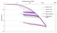
[[File:10_Wechselwirkung_B_B_02.jpg|200px|thumb|right|Picture 3: Ension settlement curves from the oedometer test and subsequent FEM calculation]] | [[File:10_Wechselwirkung_B_B_02.jpg|200px|thumb|right|Picture 3: Ension settlement curves from the oedometer test and subsequent FEM calculation]] | ||
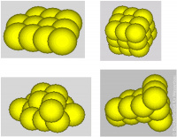
[[File:10_Wechselwirkung_B_B_03.jpg|200px|thumb|right|Picture 4: DEM simulation of armourstones ]]Depending on requirements, 2D or 3D models are designed to solve the geotechnical problem. Various different material models are available for describing the mechanical behaviour of the soil. The necessary soil characteristics can be calibrated with the results from field tests, geotechnical measurements und laboratory tests for example by numerical simulation of an oedometer experiment. Realistic computation results are obtained by visualising the complete load history of the system consisting of building structure and ground, i.e. the sequence of construction phases and conditions that are planned for implementation of the construction work. This also takes account of the changing general hydraulic conditions. Attempts are also increasingly being made to ensure that the modelling phase also takes account of the effects resulting from production of the geotechnical structures (e.g. piles, subterraneous curtains). | [[File:10_Wechselwirkung_B_B_03.jpg|200px|thumb|right|Picture 4: DEM simulation of armourstones ]]Depending on requirements, 2D or 3D models are designed to solve the geotechnical problem. Various different material models are available for describing the mechanical behaviour of the soil. The necessary soil [[characteristics]] can be calibrated with the results from [[Geotechnical field tests|field tests]], [[geotechnical measurements]] und laboratory tests for example by numerical simulation of an oedometer experiment. Realistic computation results are obtained by visualising the complete load history of the system consisting of [[building]] structure and ground, i.e. the sequence of construction phases and conditions that are planned for implementation of the construction work. This also takes account of the changing general hydraulic conditions. Attempts are also increasingly being made to ensure that the modelling phase also takes account of the effects resulting from production of the geotechnical structures (e.g. piles, subterraneous curtains). | ||
DEM offers the possibility of overcoming the limits of FEM when it comes to large net deformation when dealing with geometric bodies such as boulders or spheres. In many cases, the calculations can be simplified by concentrating on spherical shapes which are then put together to generate other geometries such as polygonal armourstones. | DEM offers the possibility of overcoming the limits of FEM when it comes to large net deformation when dealing with geometric bodies such as boulders or spheres. In many cases, the calculations can be simplified by concentrating on spherical shapes which are then put together to generate other geometries such as polygonal armourstones. | ||
Latest revision as of 01:11, 22 October 2022

Deformation and stability calculations for building structures used in waterways engineering are increasingly carried out using the finite element method (FEM) and in recent years also the distinct element method (DEM). The advantage of FEM is that it can be used to visualize complex geometries and ground conditions, and also indicates interaction between building structure and the ground.

The aforementioned advantages of the method play an important role particularly in view of the increasing complexity of construction work, for example when building excavation pits right next to structures that are susceptible to deformation during the construction of new structures next to existing locks while the waterway continues normal shipping operations, or during subsequent calculation of load-bearing and deformation behaviour of existing building structures.


Depending on requirements, 2D or 3D models are designed to solve the geotechnical problem. Various different material models are available for describing the mechanical behaviour of the soil. The necessary soil characteristics can be calibrated with the results from field tests, geotechnical measurements und laboratory tests for example by numerical simulation of an oedometer experiment. Realistic computation results are obtained by visualising the complete load history of the system consisting of building structure and ground, i.e. the sequence of construction phases and conditions that are planned for implementation of the construction work. This also takes account of the changing general hydraulic conditions. Attempts are also increasingly being made to ensure that the modelling phase also takes account of the effects resulting from production of the geotechnical structures (e.g. piles, subterraneous curtains).
DEM offers the possibility of overcoming the limits of FEM when it comes to large net deformation when dealing with geometric bodies such as boulders or spheres. In many cases, the calculations can be simplified by concentrating on spherical shapes which are then put together to generate other geometries such as polygonal armourstones.
back to: Numerical Methods
