Systematic investigations to determine speed-dependent sway forces and yaw torques caused by the bank effect when a ship passes approach channels
From BAWiki
Author: K. Uliczka
Boundary conditions
The model tests to determine the speed-dependent sway forces and yaw torques that are generated by the Bernoulli flow effects (also known as the bank effect in nautical circles) and that act on a ship, not least depending on the passing clearance between ship and embankment, were conducted in BAW-DH’s shallow water basin (length approx. 100 m, width approx. 35 m, max. water depth 0.7 m) in 1:40 scale in accordance with Froude’s model laws. The results of the tests from the hydraulic model have been scaled up accordingly and are given as prototype-size.
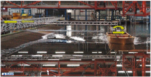
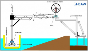
This meant that, in addition to the schematic embankments to be investigated, a corresponding guidance system (rail system with triangular guide arm) had to be installed via which the model ship could be guided and the sway and yaw acting on the ship could be measured with a redundant setup. A photograph of the system installed together with a schematic illustration of the effective sway forces and yaw torques recorded is shown in Figure 1.
The model ships were activated via wireless remote control and were self-propelled (propeller drive) with a hard trim. Their freedom of lateral movement (sway force, yaw torque) was restricted by the guide arm, while they were free to move vertically (squat and trim). The friction caused by the guide carriage against the rail system was offset by means of a separate air-propeller drive.
The chart in Figure 2 is a simplified schematic illustration of the guidance and measurement system as well as the configuration of the measurements. A scales for six degrees of freedom had been installed at the toe of the member on board the ship to record the sway forces and yaw torques. Redundantly installed force sensors in the hull and on the guide carriage provided additional measurement and checking of the results from the central scales.
Table 1 lists the ship units investigated together with their dimensions, the block coefficient and the water depths traversed. The under-keel clearance at rest UKCR had been set at 10%, 15% and 20% of the draught (1.1 < h/t < 1.2).
| Designation | Beam b [m] | Length lpp [m] | Draught t [m] | Block coefficient cB [-] | Water depths h [m] | UKCR f(t) [%] |
| PPM55 | 55.0 | 360 | 14.5 | 0.689 | 16.0/16.7/17.4 | 10/15/20 |
| PM32 | 32.2 | 280 | 11.9 | 0.671 | 13.1/13.7/14.3 | |
| MG32 | 32.2 | 225 | 11.9 | 0.845 | 13.1/13.7/14.3 |
Table 1: Ship units and parameters investigated
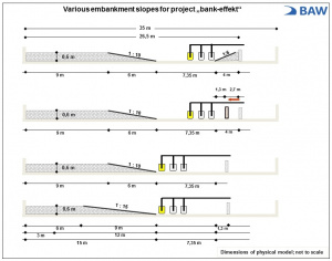
The various embankment gradients investigated of 1:6, 1:10 and 1:15 including the vertical wall and the passing clearances for the model ships are all illustrated schematically in Figure 3 (not to scale).
The clearances between the centreline of the ship and the foot of the respective embankment KBF or the vertical wall KW as well as the extent of the partial cross-sectional ratios nT investigated are shown in Table 2.
| Designation | Gradient 1:6 Clearance KBF</sub [m] | Gradient 1:10 Clearance KBF [m] | Gradient 1:15 Clearance KBF [m] | Wall Clearance KW [m] | nT = AT / 0.5 AS [-] |
| PPM55 | 27.5/82/128 | 32/72/112 | 32/72/112 | 139 / 178 | 3.1 to 10.8 |
| PM32 | 4.7 to 16.7 | ||||
| MG32 | 4.7 to 16.7 |
where: AT = partial-cross-section of the wetted area of waterway = f(KBF, KW), AS = submerged midship cross-section Table 2: Clearances investigated and extent of partial-cross-sectional ratios nT
A predefined investigation matrix produced 78 series of tests, which meant some 7,800 individual tests in all as the respective ship speeds of between approx. 8 kn < vS < approx. 14 kn were run twice and the maximum possible speeds based on the draught and waterway construction cross-section were run three times for each series to ensure the validity of the results.
Selected results
The following charts illustrate selected examples of the yaw torque and sway force of a PPM container ship drawn from the extensive investigation results from the hydraulic model. They show the speed-dependent mean values for the various time series measured over 1.5 ship lengths on both sides of the measurement cross-section defined (3 x l) as well as the corresponding standard deviations.
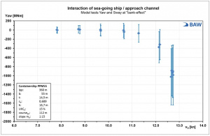
Figure 4 shows the ship-dependent yaw torque measured for a container ship with beam b = 55 m passing alongside a 1:15 embankment with a clearance of KS,BF = 112 m to the foot of the embankment and an under-keel clearance of UKCR = 15% of its draught t = 14.5 m. From a ship speed of around vS > 11 kn onwards, the yaw torque stops increasing slowly and instead begins rising disproportionately sharply, reaching values of around 1,000 MNm (vS ≈ 12.8 kn). The speed-dependent increase in the value spread up to ± 67% of the mean value at a ship speed of vS ≈ 12.8 kn highlights the significant extent of the transient flow conditions between ship and bank.
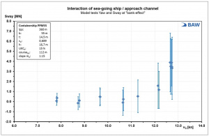
The sway forces generated by the bank effect and measured in the same test series are shown in Figure 5 together with their standard deviations. As with the speed-dependent trend in yaw torque, the sway force also increases disproportionately sharply upwards of a ship speed of around vS > 11 kn up to the maximum ship speed of vS ≈ 12.8 kn assuming the same boundary conditions as above, at which point values of some 4 MN are recorded.
In the case of the sway force generated by the bank effect, the turbulent, transient flow conditions produced standard deviations of the same order of magnitude as the mean value itself at virtually all ship speeds.
Conclusions
The results presented from the model tests to determine the speed-dependent sway forces and yaw torques generated by the Bernoulli flow effects (bank effects) highlight the impact that ship speed has once a critical speed has been passed, which triggers a disproportionately sharp increase in the hydrodynamic sway forces and yaw torques. The turbulent, unsteady flow conditions between ship and embankment produce major standard deviations around the mean values for the forces and torques acting on the ship.
The extensive data sets from the hydraulic model tests on the bank effect have been compiled into a database so that the results can serve as underlying data for a project to optimise the Ship Handling Simulation.
Back to Ship Dynamics

